


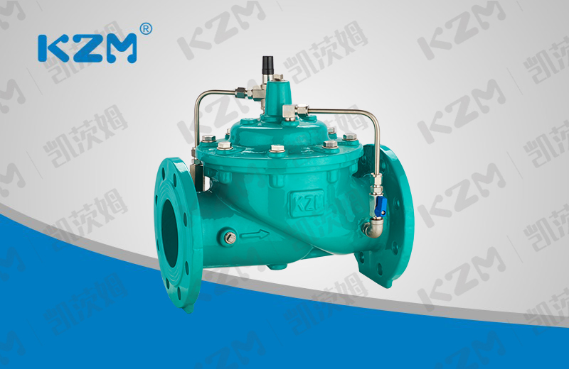
300X Slow closing check valve
Product overview
Product model: 300X
Nominal diameter: DN50-DN600
Nominal pressure: PN1.0MPa-4.0MPa
Applicable medium: water and oil
Applicable temperature: 0-90 ℃
Manufacturing standard: JB / T10674-2006
Structure length: CJ / T 219-2017
Test standard: GB / T13927-2008
Main materials: cast iron, nodular cast iron, cast steel, stainless steel
Product overview
300X Slow closing check valve is a check valve that uses the control of the medium's own pressure to realize the delayed closing function, so as to eliminate or alleviate the water hammer. It is an intelligent valve installed at the pump outlet of water supply system of high-rise buildings and other water supply systems to prevent medium backflow, water hammer and water hammer. The valve has three functions: electric valve, check valve and water hammer eliminator, which can effectively improve the safety and reliability of the water supply system, integrate the technical principles of slow opening, quick closing and slow closing to eliminate water hammer, and prevent the generation of water hammer when starting and stopping the pump.
Product features
1. 300X slow closing check valve consists of main valve, pilot valve, needle valve, ball valve and pressure gauge. Using hydraulic automatic operation, the opening or closing speed of the main valve can be obtained. Prevent water hammer and water hammer to achieve the effect of slow closing and silencing.
2. 300X slow closing check valve this product uses hydraulic control, does not need other devices and energy, simple maintenance, stable opening and slow closing. The valve is widely used in high-rise buildings, living quarters and other water supply pipe network systems and urban water supply projects.
3. When the valve supplies water from the inlet end, the water enters the main valve control room through the filter, needle valve and one-way valve, and then drains to the downstream through the ball valve. Because the opening of the needle valve is less than that of the ball valve, that is, the drainage speed of the main valve control room is greater than the water inlet speed, the pressure in the control room decreases, and the inlet pressure acting on the lower end of the main valve disc opens the main valve to supply water downstream.
4. When the water supply of the pipeline stops, if the downstream water begins to return, part of the return water enters the main control room through the ball valve. Due to the action of the one-way valve, the return water cannot flow out of the main control room, causing the main control room to gradually increase the pressure and slowly close the main valve.

Main overall connection dimensions
| DN | L | H | D | D1 | N-Φd | |||||||||
| PN10 | PN16 | PN25 | PN40 | PN10 | PN16 | PN25 | PN40 | PN10 | PN16 | PN25 | PN40 | |||
| 50 | 241 | 139 | 165 | 165 | 165 | 165 | 125 | 125 | 125 | 125 | 4-Φ19 | 4-Φ19 | 4-Φ19 | 4-Φ19 |
| 65 | 234 | 159 | 185 | 185 | 185 | 185 | 145 | 145 | 145 | 145 | 8-Φ19 | 8-Φ19 | 8-Φ19 | 8-Φ19 |
| 80 | 280 | 179 | 200 | 200 | 200 | 200 | 160 | 160 | 160 | 160 | 8-Φ19 | 8-Φ19 | 8-Φ19 | 8-Φ19 |
| 100 | 360 | 214 | 220 | 220 | 235 | 235 | 180 | 180 | 190 | 190 | 8-Φ19 | 8-Φ19 | 8-Φ23 | 8-Φ23 |
| 125 | 430 | 275 | 250 | 250 | 270 | 270 | 210 | 210 | 220 | 220 | 8-Φ19 | 8-Φ19 | 8-Φ28 | 8-Φ28 |
| 150 | 455 | 333 | 285 | 285 | 300 | 300 | 240 | 240 | 250 | 250 | 8-Φ23 | 8-Φ23 | 8-Φ28 | 8-Φ28 |
| 200 | 585 | 407 | 340 | 340 | 360 | 375 | 295 | 295 | 310 | 320 | 8-Φ23 | 12-Φ23 | 12-Φ28 | 12-Φ31 |
| 250 | 790 | 476 | 395 | 405 | 425 | – | 350 | 355 | 370 | – | 12-Φ23 | 12-Φ28 | 12-Φ31 | – |
| 300 | 900 | 526 | 445 | 460 | 485 | – | 400 | 410 | 430 | – | 12-Φ23 | 12-Φ28 | 16-Φ31 | – |
| 350 | 900 | 580 | 505 | 520 | 555 | – | 460 | 470 | 490 | – | 16-Φ23 | 16-Φ28 | 16-Φ34 | – |
Main overall connection dimensions
| DN | L | H | D | D1 | N-Φd | |||
| PN10 | PN16 | PN10 | PN16 | PN10 | PN16 | |||
| 400 | 962 | 670 | 565 | 580 | 515 | 525 | 16-Φ28 | 16-Φ31 |
| 500 | 1076 | 790 | 670 | 715 | 620 | 650 | 20-Φ28 | 20-Φ34 |
| 600 | 1232 | 930 | 780 | 840 | 725 | 770 | 20-Φ31 | 20-Φ37 |
Note: the flange size in this table is in accordance with GB / T 17241.6-2008, and the structural length is in accordance with CJ / T 219-2017.


 Jing12011202000600
