500X Safety holding / relief valve
Product overview
Product model: 500X
Nominal diameter: DN50-DN350
Nominal pressure: PN1.0MPa-4.0MPa
Applicable medium: water and oil
Applicable temperature: 0-90℃
Manufacturing standard: JB / T10674-2006
Structure length: CJ / T 219-2017
Test standard: GB / T13927-2008
Main materials: cast iron, nodular cast iron, cast steel, stainless steel
Product overview
The 500X Safety pressure holding / relief valve uses the water force to control the pilot valve to make the main valve automatically discharge part of the water to stabilize the design pressure of the pipeline in front of the valve. When the pressure returns below the set value, the main valve will close automatically, and the pressure relief and holding of the valve can be adjusted within a certain range. 500X safety pressure relief valve is mainly used in fire fighting or other water supply systems to prevent system overpressure or maintain the pressure of fire water supply system. The impact of water hammer can also be reduced after the fire pump is turned off. It is also used for water hammer device of large water supply system.
Product features
1. 500X Pressure holding / relief valve consists of main valve, pressure relief / pressure holding pilot valve, needle valve, ball valve and pressure gauge. Using hydraulic automatic operation, it can be used as both pressure relief valve and pressure holding valve. When it is used as a pressure relief valve, it can maintain the pressure of the water supply circuit below the set safety value; when it is used as a pressure holding valve, it can maintain the upstream water pressure of the main valve above the set value and maintain the upstream water supply pressure of the main valve.
2. As pressure relief valve: when the pressure relief / pressure holding pilot valve is adjusted to the pressure relief state, water flows to the outlet through needle valve, main valve control room, ball valve a, pressure relief / pressure holding pilot valve and ball valve B. at this time, the main valve is open. When the inlet pressure exceeds the safety value set by the pressure relief / pressure holding pilot valve, the pressure relief valve will close automatically. When used as pressure relief valve, each ball valve is normally open.
3. As a pressure holding valve: when the pressure relief / pressure holding pilot valve is adjusted to the pressure holding state, the pilot valve will be closed as long as the inlet water pressure of the main valve is lower than the set value of the pilot valve. The main control room is boosted and the main valve is closed. When the upstream water supply pressure of the main valve exceeds the set pressure of the pilot valve, the pressure holding pilot valve can be opened. The water in the control room is discharged to the outlet through the ball valve. The pressure reducing main valve in the control room is opened to start water supply, that is, the upstream water pressure is maintained.

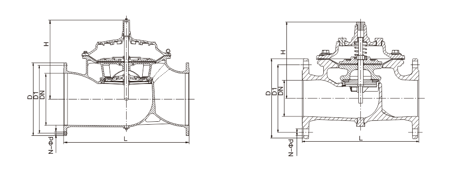
Main overall connection dimensions
| DN | L | H | D | D1 | N-Φd | |||||||||
| PN10 | PN16 | PN25 | PN40 | PN10 | PN16 | PN25 | PN40 | PN10 | PN16 | PN25 | PN40 | |||
| 50 | 241 | 139 | 165 | 165 | 165 | 165 | 125 | 125 | 125 | 125 | 4-Φ19 | 4-Φ19 | 4-Φ19 | 4-Φ19 |
| 65 | 234 | 159 | 185 | 185 | 185 | 185 | 145 | 145 | 145 | 145 | 8-Φ19 | 8-Φ19 | 8-Φ19 | 8-Φ19 |
| 80 | 280 | 179 | 200 | 200 | 200 | 200 | 160 | 160 | 160 | 160 | 8-Φ19 | 8-Φ19 | 8-Φ19 | 8-Φ19 |
| 100 | 360 | 214 | 220 | 220 | 235 | 235 | 180 | 180 | 190 | 190 | 8-Φ19 | 8-Φ19 | 8-Φ23 | 8-Φ23 |
| 125 | 430 | 275 | 250 | 250 | 270 | 270 | 210 | 210 | 220 | 220 | 8-Φ19 | 8-Φ19 | 8-Φ28 | 8-Φ28 |
| 150 | 455 | 333 | 285 | 285 | 300 | 300 | 240 | 240 | 250 | 250 | 8-Φ23 | 8-Φ23 | 8-Φ28 | 8-Φ28 |
| 200 | 585 | 407 | 340 | 340 | 360 | 375 | 295 | 295 | 310 | 320 | 8-Φ23 | 12-Φ23 | 12-Φ28 | 12-Φ31 |
| 250 | 790 | 476 | 395 | 405 | 425 | – | 350 | 355 | 370 | – | 12-Φ23 | 12-Φ28 | 12-Φ31 | – |
| 300 | 900 | 526 | 445 | 460 | 485 | – | 400 | 410 | 430 | – | 12-Φ23 | 12-Φ28 | 16-Φ31 | – |
| 350 | 900 | 580 | 505 | 520 | 555 | – | 460 | 470 | 490 | – | 16-Φ23 | 16-Φ28 | 16-Φ34 | – |
Main overall connection dimensions
| DN | L | H | D | D1 | N-Φd | |||
| PN10 | PN16 | PN10 | PN16 | PN10 | PN16 | |||
| 400 | 962 | 670 | 565 | 580 | 515 | 525 | 16-Φ28 | 16-Φ31 |
| 500 | 1076 | 790 | 670 | 715 | 620 | 650 | 20-Φ28 | 20-Φ34 |
| 600 | 1232 | 930 | 780 | 840 | 725 | 770 | 20-Φ31 | 20-Φ37 |
Note: the flange size in this table is in accordance with GB / T 17241.6-2008, and the structural length is in accordance with CJ / T 219-2017.


 Jing12011202000600
