200X Adjustable pressure reducing valve
Product overview
Product model: 200X
Nominal diameter: DN50-dn600
Nominal pressure: PN1 0MPa-4.0MPa
Applicable medium: water and oil
Applicable temperature: 0-90 ℃
Manufacturing standard: JB / T10674-2006
Structure length: CJ / T 219-2017
Test standard: GB / T13927-2008
Material selection: cast iron, nodular cast iron, cast steel, stainless steel
Product overview
200X Adjustable pressure reducing valve is a valve that reduces the inlet pressure to a required outlet through the throttling of the opening and closing parts, and can use the energy of the medium itself to keep the outlet pressure basically unchanged when the inlet pressure and flow change. It is applicable to the water supply system in which fire water and domestic water are connected in parallel, and is used to allocate the valve in the water supply direction. In case of fire, fire fighting is in urgent need of a large amount of water, and domestic water shall be cut off immediately to ensure sufficient fire water; When the pressure of fire water is reduced, the valve will automatically open and be normally open to restore domestic water supply.
Product features
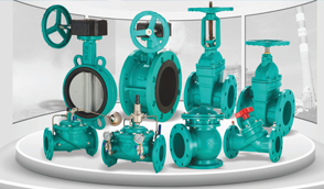
1. The valve consists of main valve, pilot valve, needle valve, ball valve and pressure gauge. When in use, when the outlet pressure is set, it can automatically maintain a stable outlet pressure.
2. This product is self controlled by pilot valve, without other devices and energy, simple maintenance, high accuracy of pressure control, less affected by inlet pressure and flow, and reliable pressure reduction and stabilization. The valve is widely used in high-rise buildings, living quarters and other water supply pipe network systems and urban water supply projects.
working principle
When the valve supplies water from the inlet end, water flows through the needle valve into the main valve control room and establishes downward pressure. The outlet pressure acts under the diaphragm of the pilot valve through the conduit and opposes the force of the regulating spring of the pilot valve. When the outlet pressure is higher than the set value of the pilot valve spring, the pilot valve is closed, the water displacement in the control room is zero, and the pressure increases by a large value, the main valve disc presses the valve seat tightly, and the pressure reducing valve is closed. When the outlet pressure of the valve drops to the set pressure of the pilot valve spring, the pilot valve opens and the water in the control room is discharged downstream through the pilot valve. In the stable regulation state, the discharge flow is equal to the make-up flow, the opening of the main valve remains unchanged, and the downstream pressure is stable.

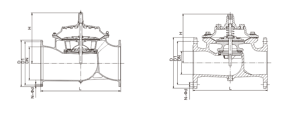
Main overall connection dimensions
| DN | L | H | D | D1 | N-Φd | |||||||||
| PN10 | PN16 | PN25 | PN40 | PN10 | PN16 | PN25 | PN40 | PN10 | PN16 | PN25 | PN40 | |||
| 50 | 241 | 139 | 165 | 165 | 165 | 165 | 125 | 125 | 125 | 125 | 4-Φ19 | 4-Φ19 | 4-Φ19 | 4-Φ19 |
| 65 | 234 | 159 | 185 | 185 | 185 | 185 | 145 | 145 | 145 | 145 | 8-Φ19 | 8-Φ19 | 8-Φ19 | 8-Φ19 |
| 80 | 280 | 179 | 200 | 200 | 200 | 200 | 160 | 160 | 160 | 160 | 8-Φ19 | 8-Φ19 | 8-Φ19 | 8-Φ19 |
| 100 | 360 | 214 | 220 | 220 | 235 | 235 | 180 | 180 | 190 | 190 | 8-Φ19 | 8-Φ19 | 8-Φ23 | 8-Φ23 |
| 125 | 430 | 275 | 250 | 250 | 270 | 270 | 210 | 210 | 220 | 220 | 8-Φ19 | 8-Φ19 | 8-Φ28 | 8-Φ28 |
| 150 | 455 | 333 | 285 | 285 | 300 | 300 | 240 | 240 | 250 | 250 | 8-Φ23 | 8-Φ23 | 8-Φ28 | 8-Φ28 |
| 200 | 585 | 407 | 340 | 340 | 360 | 375 | 295 | 295 | 310 | 320 | 8-Φ23 | 12-Φ23 | 12-Φ28 | 12-Φ31 |
| 250 | 790 | 476 | 395 | 405 | 425 | – | 350 | 355 | 370 | – | 12-Φ23 | 12-Φ28 | 12-Φ31 | – |
| 300 | 900 | 526 | 445 | 460 | 485 | – | 400 | 410 | 430 | – | 12-Φ23 | 12-Φ28 | 16-Φ31 | – |
| 350 | 900 | 580 | 505 | 520 | 555 | – | 460 | 470 | 490 | – | 16-Φ23 | 16-Φ28 | 16-Φ34 | – |
Main overall connection dimensions
| DN | L | H | D | D1 | N-Φd | |||
| PN10 | PN16 | PN10 | PN16 | PN10 | PN16 | |||
| 400 | 962 | 670 | 565 | 580 | 515 | 525 | 16-Φ28 | 16-Φ31 |
| 500 | 1076 | 790 | 670 | 715 | 620 | 650 | 20-Φ28 | 20-Φ34 |
| 600 | 1232 | 930 | 780 | 840 | 725 | 770 | 20-Φ31 | 20-Φ37 |
Note: The flange dimensions in this table are in accordance with the GB/T 17241.6-2008 standard, and the structure length is in accordance with the CJ/T 219-2017 standard.


 Jing12011202000600
