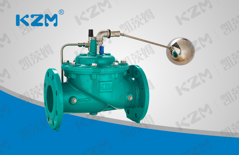
100X Remote control float valve
Technical Parameter
Product model: 100X
Nominal diameter: DN50-DN600
Nominal pressure: PN1.0MPa-4.0MPa
Applicable medium: water and oil
Applicable temperature: 0-90 ℃
Manufacturing standard: JB / T10674-2006
Structure length: CJ / T 219-2017
Test standard: GB / T13927-2008
Main materials: cast iron, nodular cast iron, cast steel, stainless steel
Product overview
100X Remote control float valve is a hydraulic operated valve with multiple functions, which uses the rise and fall of the float ball in the control circuit to control the opening and closing of the main valve to automatically control the set liquid level. It can effectively control the liquid level of water tower or water tank, and is suitable for connecting or cutting off the fluid in the pipeline. The liquid level control is accurate, the water level is not disturbed by pressure fluctuation, the opening and closing is flexible, the sealing is reliable, the service life is long, and the maintenance is simple. It is suitable for automatic water supply system of water tank, pool and water tower in high-rise buildings.
Product features
1. The remote control floating ball valve is composed of main valve, ball valve and floating ball valve. After setting, the liquid level is automatically controlled. Direct use of liquid level control, without other devices and energy, simple maintenance, high accuracy of liquid level control, not affected by water pressure and reliable sealing.
2. When the pipeline supplies water from the inlet end, because the ball valve and ball valve are normally open, the water enters the pool through needle valve, control room, ball valve and ball valve. Therefore, there is no pressure in the control room, the main valve is opened and the water tower supplies water.
3. When the water surface of the water tower rises to the set height, the float valve floats up, closes the float valve, the water pressure in the control room rises, pushes the main valve to close, and the water supply stops. When the water level drops, the float valve is reopened, the water pressure in the control room drops, the main valve is opened again to continue water supply and maintain the set height of the liquid level.

Main overall connection dimensions
| DN | L | H | D | D1 | N-Φd | |||||||||
| PN10 | PN16 | PN25 | PN40 | PN10 | PN16 | PN25 | PN40 | PN10 | PN16 | PN25 | PN40 | |||
| 50 | 241 | 139 | 165 | 165 | 165 | 165 | 125 | 125 | 125 | 125 | 4-Φ19 | 4-Φ19 | 4-Φ19 | 4-Φ19 |
| 65 | 234 | 159 | 185 | 185 | 185 | 185 | 145 | 145 | 145 | 145 | 8-Φ19 | 8-Φ19 | 8-Φ19 | 8-Φ19 |
| 80 | 280 | 179 | 200 | 200 | 200 | 200 | 160 | 160 | 160 | 160 | 8-Φ19 | 8-Φ19 | 8-Φ19 | 8-Φ19 |
| 100 | 360 | 214 | 220 | 220 | 235 | 235 | 180 | 180 | 190 | 190 | 8-Φ19 | 8-Φ19 | 8-Φ23 | 8-Φ23 |
| 125 | 430 | 275 | 250 | 250 | 270 | 270 | 210 | 210 | 220 | 220 | 8-Φ19 | 8-Φ19 | 8-Φ28 | 8-Φ28 |
| 150 | 455 | 333 | 285 | 285 | 300 | 300 | 240 | 240 | 250 | 250 | 8-Φ23 | 8-Φ23 | 8-Φ28 | 8-Φ28 |
| 200 | 585 | 407 | 340 | 340 | 360 | 375 | 295 | 295 | 310 | 320 | 8-Φ23 | 12-Φ23 | 12-Φ28 | 12-Φ31 |
| 250 | 790 | 476 | 395 | 405 | 425 | – | 350 | 355 | 370 | – | 12-Φ23 | 12-Φ28 | 12-Φ31 | – |
| 300 | 900 | 526 | 445 | 460 | 485 | – | 400 | 410 | 430 | – | 12-Φ23 | 12-Φ28 | 16-Φ31 | – |
| 350 | 900 | 580 | 505 | 520 | 555 | – | 460 | 470 | 490 | – | 16-Φ23 | 16-Φ28 | 16-Φ34 | – |
Main overall connection dimensions
| DN | L | H | D | D1 | N-Φd | |||
| PN10 | PN16 | PN10 | PN16 | PN10 | PN16 | |||
| 400 | 962 | 670 | 565 | 580 | 515 | 525 | 16-Φ28 | 16-Φ31 |
| 500 | 1076 | 790 | 670 | 715 | 620 | 650 | 20-Φ28 | 20-Φ34 |
| 600 | 1232 | 930 | 780 | 840 | 725 | 770 | 20-Φ31 | 20-Φ37 |
Note: the flange size in this table is in accordance with GB / T 17241.6-2008, and the structural length is in accordance with CJ / T 219-2017.







 Jing12011202000600
